
Multi-tier application on private networks
Most production setups need the same four things: one public entry point for traffic, tiers that cannot reach each other except where you allow it, one shared path out to the internet, and a controlled way to administer the servers.
To meet these needs, this architecture uses a Managed Load Balancer as the public entry point, SDN Private Networks and the SDN Firewall to keep the tiers apart, an SDN Router and a NAT Gateway for one shared path out, and an admin host for administration.
This page shows how to combine them, using an example with two tiers: a front tier that receives web traffic through a Managed Load Balancer, and a restricted tier that accepts only one type of connection from the front tier. An admin host on its own small network is the only way to reach the servers over SSH.
The tier names are roles, not products. Your front tier might run web servers and your restricted tier a database, or something else entirely. The pattern stays the same, and you can change the number of servers or add tiers, as described in Adapt the design.
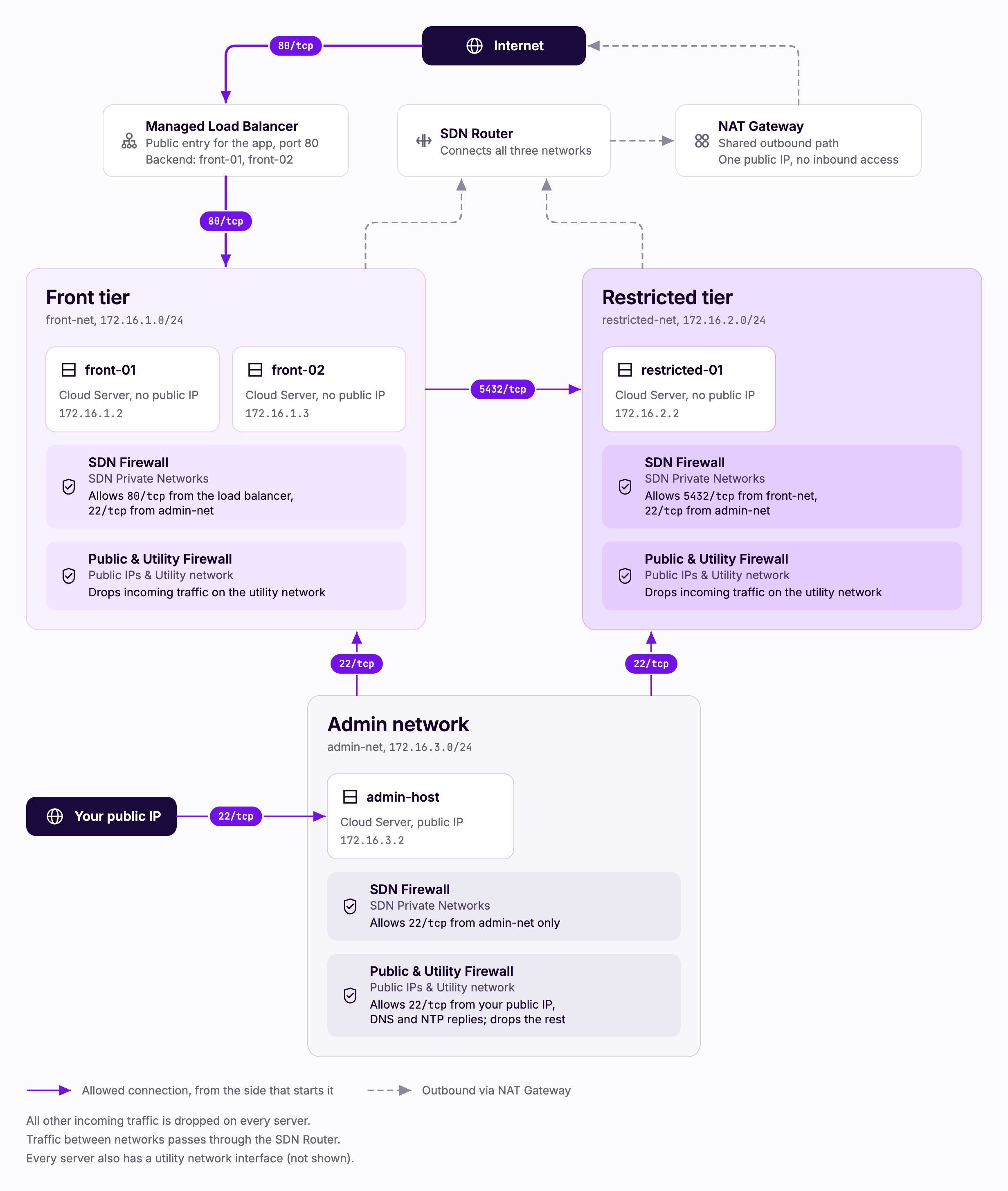
With this design in place:
- The internet can reach your application only through the load balancer on port 80, and can reach the admin host only on port 22. For production, serve your application over HTTPS as well, as described in HTTPS in production.
- The admin host can reach both tiers on port 22 and nothing else. The tiers cannot reach the admin host.
- The front tier can reach the restricted tier on port 5432 only. Nothing else crosses between the tiers, in either direction, on the private networks or over the utility network.
- Servers in the same tier cannot reach each other either. Port 80 on the front tier accepts only the load balancer's own addresses.
- Both tiers can reach the internet outbound through the NAT Gateway, so none of the tier servers needs a public IP address.
When to use this pattern
This pattern fits workloads that:
- Need a single public entry point with everything else kept private, such as a web tier in front of a database or an internal API.
- Need clear boundaries between components, so that a problem in one tier cannot spread to another.
- Need outbound internet access for updates or external services without giving servers public IP addresses.
It does not fit setups where servers need to be reachable directly from the internet on their own public IP addresses.
Products used
| Product | Role in this design | Documentation |
|---|---|---|
| SDN Private Networks | One network per tier, and one for the admin host | Configure SDN Private Networks |
| SDN Router | Connects the tier networks and carries traffic out to the NAT Gateway | Connect private networks using SDN Router |
| SDN Firewall | Controls which traffic can cross between and within tiers on the private networks | Firewall |
| Public & Utility Firewall | Closes the utility network, which the SDN Firewall does not cover, and opens SSH on the admin host | Firewall |
| NAT Gateway | Shared outbound path for the tiers, with no inbound access | Connect a private server to the internet using NAT Gateway |
| Cloud Server (admin host) | A server with a public IP address on its own network, and the only SSH path to the tiers | Cloud Servers |
| Managed Load Balancer | The only inbound path for application traffic, from the internet to the front tier | Managed Load Balancer |
If you are coming from another platform
| You may know it as | On UpCloud |
|---|---|
| VLANs or subnets | SDN Private Networks |
| DNAT or port forwarding | Managed Load Balancer |
| SNAT or a NAT gateway | NAT Gateway |
| Bastion or jump host | Admin host (a Cloud Server) |
Build the design
Build the multi-tier application design lists everything to create, from the networks and router to the load balancer and firewalls, with the exact configuration of each part. Use it with any tool: the Control Panel, the API, upctl or Terraform. Use the sections below to understand what you are building and why.
Design decisions
Private ranges outside 10.0.0.0/8
Every Cloud Server has a utility network interface, and the utility network claims the whole 10.0.0.0/8 range on the server. The utility interface receives a DHCP route covering 10.0.0.0/8. If your SDN Private Networks use 10.x addresses and route auto-population is off, traffic from one network to another matches that route and leaves through the utility interface instead of your SDN Router, and the connection fails.
This design uses 172.16.1.0/24, 172.16.2.0/24 and 172.16.3.0/24. The utility route never matches, and cross-network traffic flows through the router with no extra configuration. If you need to stay on 10.x addresses, see Utility network routes.
The range of an SDN Private Network cannot overlap any other SDN Private Network in your account, including networks in other zones. If you already use 172.16.1.0/24, 172.16.2.0/24 or 172.16.3.0/24, choose other ranges outside 10.0.0.0/8. The build steps name every place the ranges appear.
Isolation comes from firewall rules
Networks attached to the same router can reach each other by default. The network layout provides connectivity and the firewalls provide isolation. With the default incoming action set to drop, only traffic matching an accept rule reaches a server on its private interfaces, including traffic from servers on the same network.
Two firewalls cover the two kinds of interface. The SDN Firewall filters each server's private interfaces. The Public & Utility Firewall filters its public and utility interfaces. Both are needed, because the utility network connects every Cloud Server in your account. In the Control Panel, the Public & Utility Firewall appears as the Public Firewall ("Public IPs & Utility network") and the SDN Firewall as the SDN Firewall ("SDN Private Networks"). A final rule that drops all incoming traffic appears as the incoming default rule, set to Drop all.
The private firewall is off on a new server, and an attached ruleset filters nothing until it is switched on. Once it is on, the default actions are drop for incoming and accept for outgoing, which gives this design its posture: nothing in unless a rule allows it, everything out. The rulesets are stateful, so replies to allowed connections are allowed automatically.
Entry and exit paths
The Managed Load Balancer is the only inbound path for application traffic. The tier servers have no public interface, so nothing else can reach them from the internet. The admin host is the only other way in, and it accepts SSH only.
The NAT Gateway handles outgoing connections only. It accepts only return traffic for connections your servers started, and all outbound traffic from both tiers leaves through its single public IP address.
An admin host on its own network
The admin host is a Cloud Server with a public IP address, on its own SDN Private Network (admin-net). It is the only server in the design that accepts connections from the internet other than through the load balancer, and it accepts SSH only. From the admin host you connect to the tier servers over their private addresses.
Keeping the admin host on its own network lets the firewalls treat it differently from both tiers. Each tier's ruleset accepts port 22 from admin-net and nothing else from it, and the admin host's own ruleset accepts port 22 from admin-net only, so servers in the tiers cannot reach the admin host on its private address. The admin host has its own routes to the tier networks, which are described in Admin host routes.
One ruleset per tier
Each tier has one firewall ruleset shared by all its servers. Adding a server to a tier means attaching the existing ruleset to it, and a rule change rolls out to the whole tier at once.
Adapt the design
The example is a starting point. You can change the number of servers in each tier, add tiers, or use a managed service where a tier's servers would go.
Change the number of servers
A tier can have one server or many. To add a server, create it on the tier's network, attach the tier's existing ruleset, switch on its private firewall and give it the same Public & Utility Firewall rules as the other servers in the tier. One ruleset shared across the tier keeps the policy in one place, and attaching it rolls the current version out to the new server.
For the front tier, also add each server to the load balancer's backend as a static member on port 80. The load balancer spreads requests across all members that pass their health checks. With a single front server, all traffic goes to that server, and there is no second server to take over if it fails.
The build steps create two front servers. Notes in steps 4, 5 and 7 cover other counts.
Add a tier
Repeat the recipe: a new network on the same router, a ruleset describing what may reach it, including port 22 from admin-net, then attach and enable. Add the new network's range to admin-net's DHCP routes so the admin host can reach it. The router and NAT Gateway are already in place and serve the new tier with no changes.
Use a managed service for a tier
A tier can also be a managed service, such as Managed PostgreSQL in place of the restricted tier's server. Attach it to the network of the servers that connect to it, such as front-net: a managed database accepts connections only from the networks it is attached to. The SDN Firewall rules in this design apply to Cloud Servers, and the database's allowed IP addresses do not filter connections from attached networks, so protect it with its users and passwords.
Things to know
Utility network routes
Every server's utility interface carries a route to 10.0.0.0/8, which is why this design uses ranges outside it. See Routes over the utility network. To use 10.x ranges instead, switch on route auto-population on each tier network. In the Control Panel, the network form has a "DHCP routes auto-population" switch, and it is on by default.
DNS servers
The tier servers have no public interface, so they resolve names only through the DNS servers set on their networks. Set both of UpCloud's resolvers on every network before you create the servers. See DNS servers, and Changing DHCP settings on running servers if you change them later.
Admin host routes
The admin host has a public interface and an interface on admin-net. The public interface provides its default route, so admin-net must not provide a second one. In this design, admin-net has its default route turned off and lists the routes to the tier networks instead. The admin host then has one default route, through its public interface, and reaches the tier networks through the router.
Through the API, the routes go in the network's dhcp_routes field. Step 1 of the build sets them when it creates admin-net.
In the Control Panel, open Network, then Private networks, and select the network. Edit IP network has the DHCP default route and DHCP routes auto-population options, and the Static DHCP routes section lists the routes. The next hop of each route is the network's gateway address.
Servers pick up changed routes when they renew their lease. See Changing DHCP settings on running servers.
Keep route auto-population off on admin-net. With a NAT Gateway on the router, auto-population also hands out the gateway's 0.0.0.0/0 route, and the admin host would get a second default route, which leaves it without a single predictable path out.
NAT Gateway route
The tier networks hand out the default route, and the NAT Gateway adds the router's 0.0.0.0/0 route, so the tier servers reach the internet through the gateway. The gateway also attaches a service network that does not appear in the list of your networks; both are part of normal operation. See The router's service route for how the route appears in the API and in Terraform.
The gateway takes several minutes to reach the running state. Wait for it before you test outbound connections.
Load balancer addresses
The load balancer's backend has both front servers as static members on port 80, and requests alternate between them. The load balancer connects to front-net on its back side and holds two private addresses there, marked "listen": true and "listen": false. Your front servers see the "listen": false address as the source of every health check and forwarded request. See Addresses on private networks.
Both addresses are assigned by DHCP when the load balancer is created, so they are only known once it is running. The front ruleset allows port 80 from these two addresses only, rather than from the whole of front-net, so no other server on front-net can reach the front servers' port 80. Step 7 of the build reads the addresses and adds the rules.
The load balancer takes several minutes to reach the running state.
Keep the utility network closed
The utility network connects every Cloud Server in your account, and the SDN Firewall does not filter it. With only the SDN Firewall in place, a server in one tier can reach a server in the other over its utility address on any port, and the tiers are not isolated.
Enable the Public & Utility Firewall on every server, with an accept rule for outgoing traffic and a final rule that drops incoming traffic. It does not see private network traffic, so the load balancer, the tier-to-tier path and the NAT Gateway keep working.
The tier servers need no SSH rule on this firewall, because the admin host connects to them over their private addresses, which only the SDN Firewall filters. Their rules are an accept rule for outgoing traffic and the final drop.
The admin host needs three more rules. SSH is accepted from your own public IP address or range only, which keeps the internet out and also stops the tier servers from reaching the admin host's SSH port over the utility network. The admin host resolves names and synchronizes its clock through its public interface. This firewall does not keep track of UDP traffic, so the replies to these queries need rules of their own: UDP from source port 53 of UpCloud's two DNS resolvers, 94.237.127.9 and 94.237.40.9, and UDP from source port 123 to ports 1024 to 65535 for time servers. Without them, DNS queries to these resolvers and NTP queries time out. The tier servers need no such rules, because their traffic leaves through the NAT Gateway and the stateful SDN Firewall admits the replies. If your address changes, update the SSH rule in the Control Panel or through the API.
Step 6 of the build creates these rules. They can take a minute or two to apply.
Reach the servers
The tier servers have no public IP address, so you reach them through the admin host. Connect to the admin host's public IP address with your SSH key, jumping to a tier server's private address in the same command:
ssh -J root@ADMIN_PUBLIC_IP [email protected]ssh -J uses your SSH agent or default key for both connections, and does not pass a key given with -i to the admin host. If your key is not in the default location, add it to your agent first with ssh-add.
Use the same SSH key on all four servers. Other servers on the utility network stay blocked, and the admin host cannot reach the application ports on the tiers.
The web console in the Control Panel also reaches the servers whatever the firewalls do, because it does not use the network. A server deployed with an SSH key has no root password, so the console shows a login prompt that you cannot pass. To use the console, first set a root password by following Regaining access to a server that was deployed using SSH keys.
HTTPS in production
This design uses a plain HTTP frontend on port 80, so that it works without a certificate or a domain name. For production traffic, serve HTTPS: add a frontend on port 443 to the load balancer and attach an SSL certificate bundle to it. You can upload an existing certificate, or have the load balancer request one for your domain, which needs a CNAME record pointing your hostname at the load balancer. See Managed Load Balancer SSL certificates for both options. The load balancer remains the only inbound path for application traffic either way.
Rolling out rule changes
Changes to a ruleset reach the servers on their own and go live as soon as they roll out, so change related rules in one request. See Change rules later in the SDN Firewall guide, and Change rules later for this design's rulesets.
Verify it works
Test every path you designed, including the ones that are supposed to fail.
| From | To | Port | Expected |
|---|---|---|---|
| internet | load balancer | 80 | works |
| internet | front-01, front-02 or restricted-01 directly | any | fails, because the tier servers have no public interface |
| internet | admin host | 22 | works from the address you allowed |
| internet | admin host | any other port | fails |
| admin host | front-01, front-02 and restricted-01, over their private addresses | 22 | works |
| admin host | front-01, front-02 and restricted-01 | 80, 5432 | fails |
| front-01 or restricted-01 | admin host, over its private or utility address | 22 | fails |
| internet | NAT Gateway public IP | any | fails, because the gateway accepts only return traffic |
| front-01 | restricted-01 | 5432 | works |
| front-01 | restricted-01 | 22, ping | fails |
| restricted-01 | front-01 | any | fails |
| front-01 | front-02 | 22, ping | fails, because same-network traffic is filtered too |
| front-01 | front-02 | 80 | fails, because port 80 accepts only the load balancer's addresses |
| front-01 | restricted-01, over its utility address | any | fails when the Public & Utility Firewall drops incoming traffic; open without it |
| front-01 or restricted-01 | internet | 443 | works, through the NAT Gateway |
Run the tests from the admin host, which reaches each tier server over its private address, as described in Reach the servers.
Servers get their private addresses by DHCP, in the order they are created, so which server has which address can differ from the diagram. Use each server's own address in the tests. The only server in restricted-net always has 172.16.2.2, and the admin host always has 172.16.3.2, because each is the first address after the gateway on a network of its own.
For the paths between servers, run a quick TCP test from a shell on the source server:
timeout 4 bash -c '</dev/tcp/172.16.2.2/5432' && echo open || echo blockedTo confirm the load balancer traffic arrives from the node address you allowed, check your service's access logs on front-01. Every request should come from the load balancer's node address.